Progressive Skew Steel Archway
Solving a client’s garden layout problem.
The Landscaping Dilemma
Our client wanted a naturally weathering architectural archway feature that will run parallel to their workshop line on one side. Unlike a traditional archway where the arch sections would normally be at 90 degrees to this line, the first arch section was required to be at 70-degrees to match the existing paving angle on the entry side, so it would not overlap the existing paving. Also, the exiting arch needed to be at the “traditional” 90 degree angle to follow the rear wall line of the workshop. These might sound like simple adjustments – Read on to discover how a mere 20 degrees changes the whole approach to design & build…
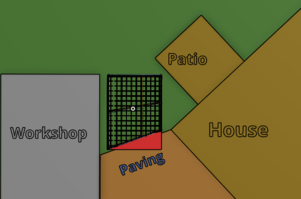
Garden Layout
What is a Progressive skew arch?
A skew arch is where the entrance and/or exit arches do not run at 90 degrees to the archway’s path.
For this archway, we started with a design where the first arch would run at 70 degrees at the entrance (to allow for the paving angle), 80 degrees for the middle arch (to ensure even spacing) and finally the 90 degree arch for the exit into the back garden, hence the name “progressive skew”.
So why is this any different to building a regular archway?
Because a regular archway has arch sections at 90 degrees to its path, each arch section will be exactly the same - same width, same radius, same elliptical sections as one another. The sidewalls of a regular archway will also be the same length. A progressive skew archway by pure geometry will require its arch sections all to be at different widths, radius dimensions, and elliptical profile lengths. The sidewalls will also be differing lengths.
The Mathematical Reality of a progressive skew arch
Archway side walls are usually perfectly parallel, the perpendicular distance (the gap) between them is completely constant. However, because the arch sections of a progressive skew archway “slice” across that gap at different angles, the following applies -
A 90-degree arch section takes the shortest possible path between two parallel lines. Structurally, its physical width is equal to the exact distance between the walls.
A 70-degree arch crosses at a sharper angle. This line slicing across two parallel lines is mathematically longer than a 90 degree (perpendicular line). Therefore, its physical span is wider.
The 80-degree (middle arch) is in between the two above, in terms of width.
Building an archway such as this to look symmetrical (when looking straight through it), requires the 70-degree arch to be wider & have a flatter curve, while the 90-degree arch will be narrower and more acute. Again, the 80-degree arch would be somewhere in between.
Design considerations
This is where things get a little more complex…
To add to the challenge of making three separate width arches to look symmetrical (when looking straight through them), our client wanted each arch section made up from four individual sections joined together with steel rings to create an open tubular effect.
This would require;
Twelve individual arch sections.
Nine different widths with nine different profiles paths to be formed accurately to ensure alignment of the entire structure.
Thirty hand-crafted steel rings to join them all together.
The structure was to be a maximum of 3.0m long x 2.0m internal width and 2.1m internal height, with the arch profile being elliptical as per our client’s requirements.
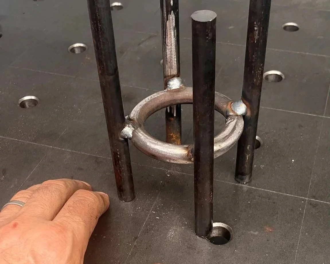
Mock up of the tubular arch section in 12mm round bar. This looked a little heavy so we decided to use 10mm round bar after consulting with the customer. This would provide a more delicate appearance to the structure that our client was looking for.
Designing to fit the space.
After measuring up and mapping of the garden layout into CAD software, we drew up the draft design and submitted to our client for any modifications and subsequent approval.
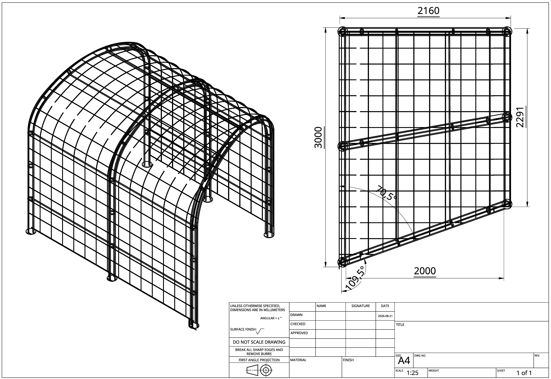
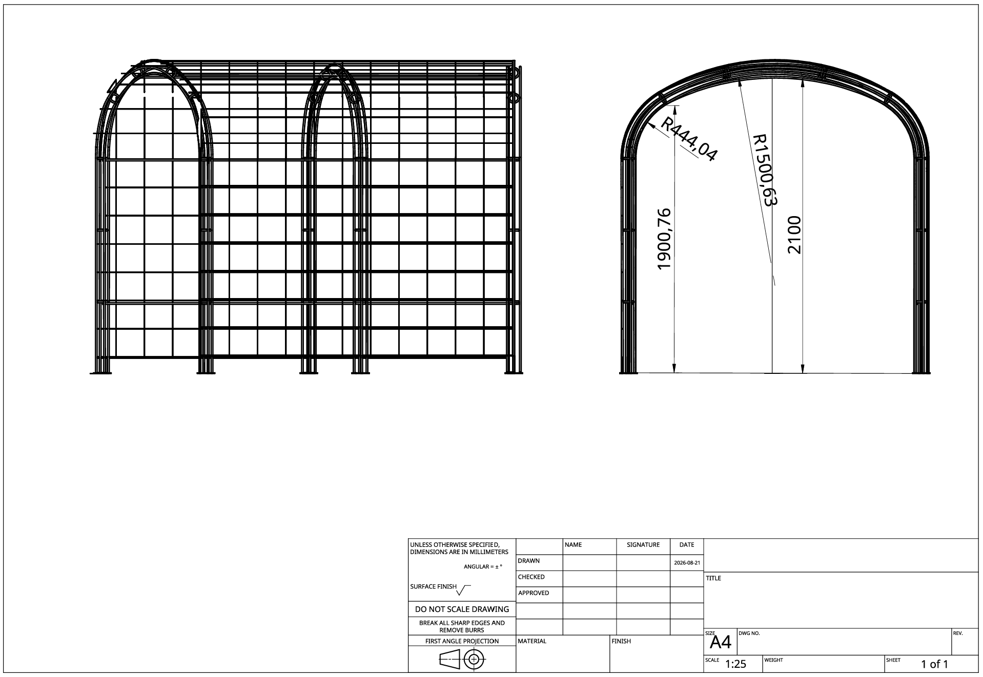
Following this, we created extrusion paths of the 90-degree arch profile and projected these through the 70- & 80-degree arch planes using the CAD drawing software.
From here, we created full scale drawings of these planes and printed them full size (yes, we really did this), then used these prints to trace the nine profile paths onto plywood to enable each profile be replicated and formed from solid steel bar. This whole process was repeated for the 70, 80 and 90 degree arch assemblies.
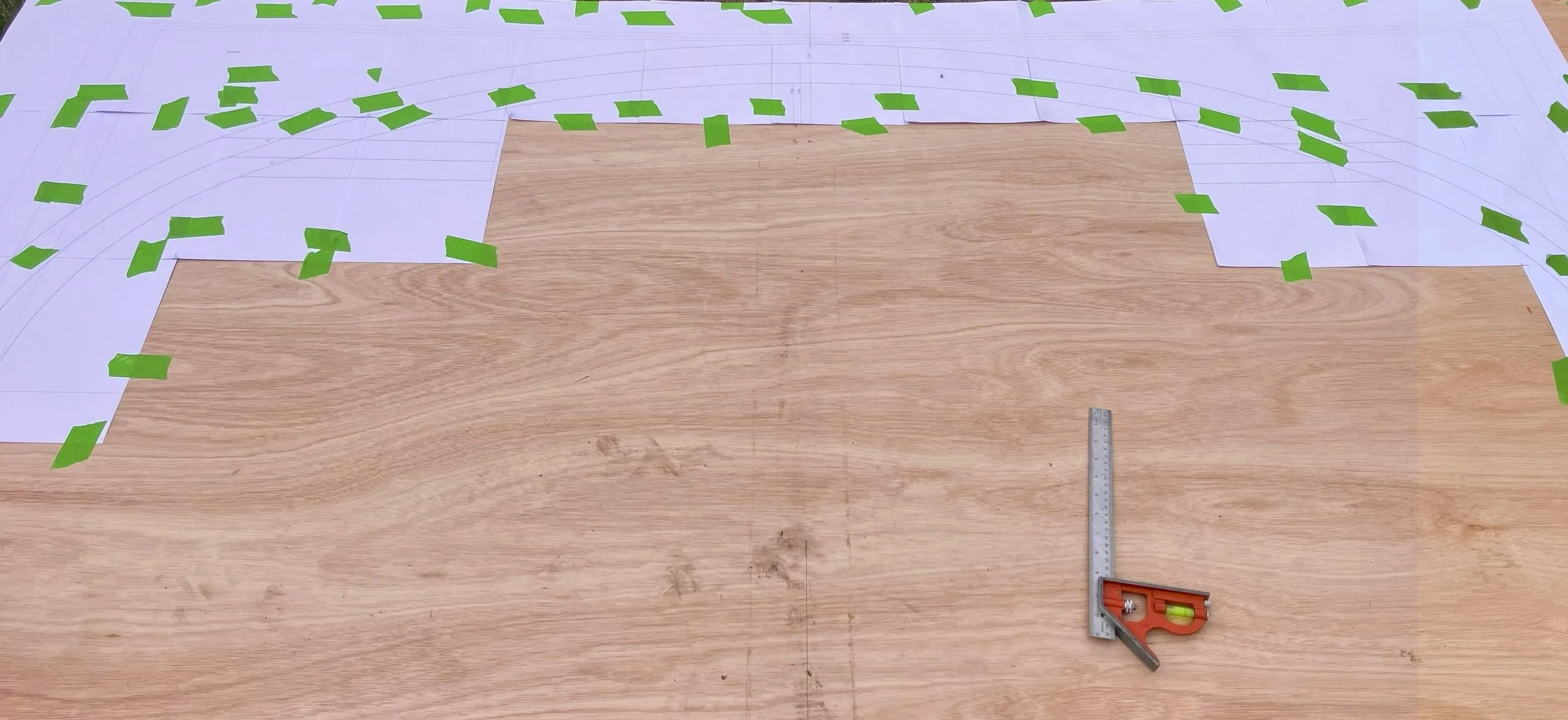
Tiling the prints full scale for the 90 degree arch section.
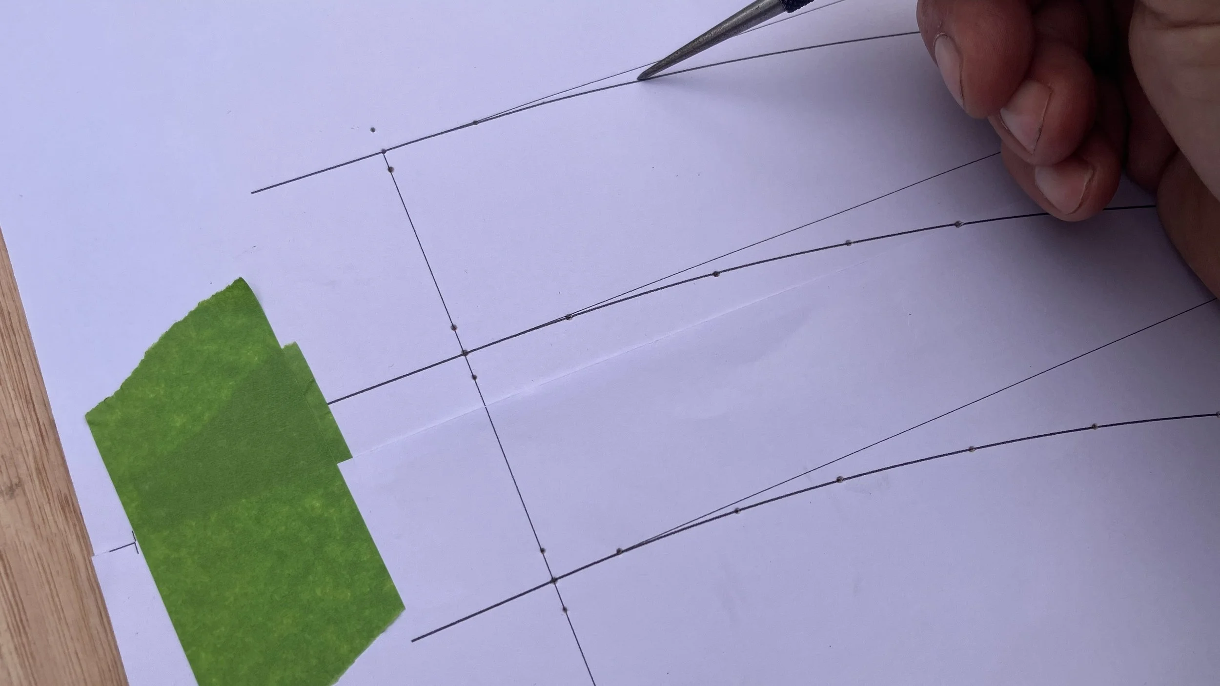
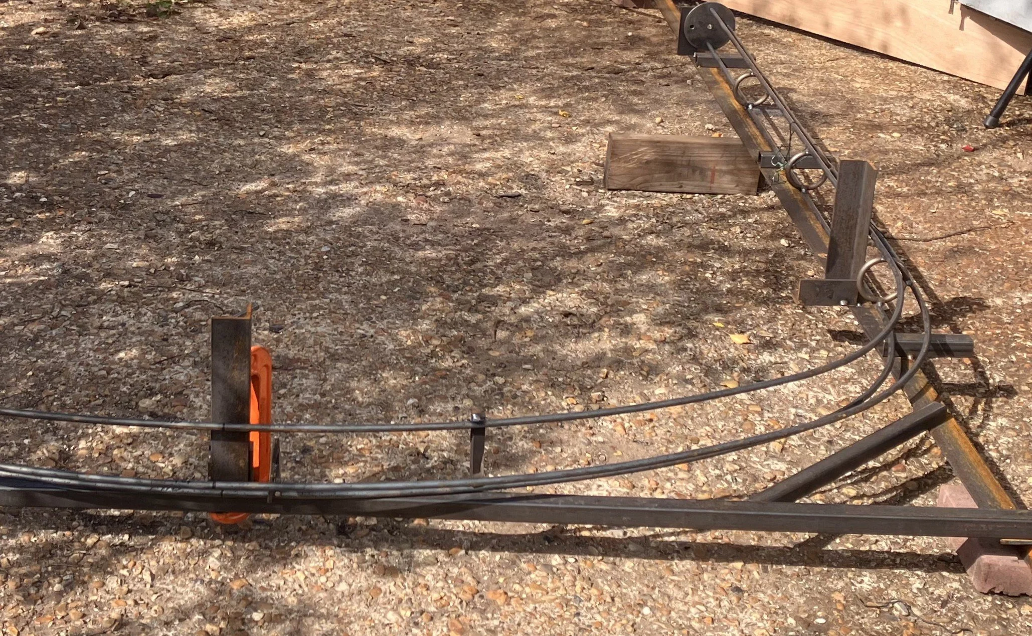
Tracing the paths for the forming process of the first arch assembly. Top path (outer frame), middle path (center frame) & bottom path being the inside frame of the archway.
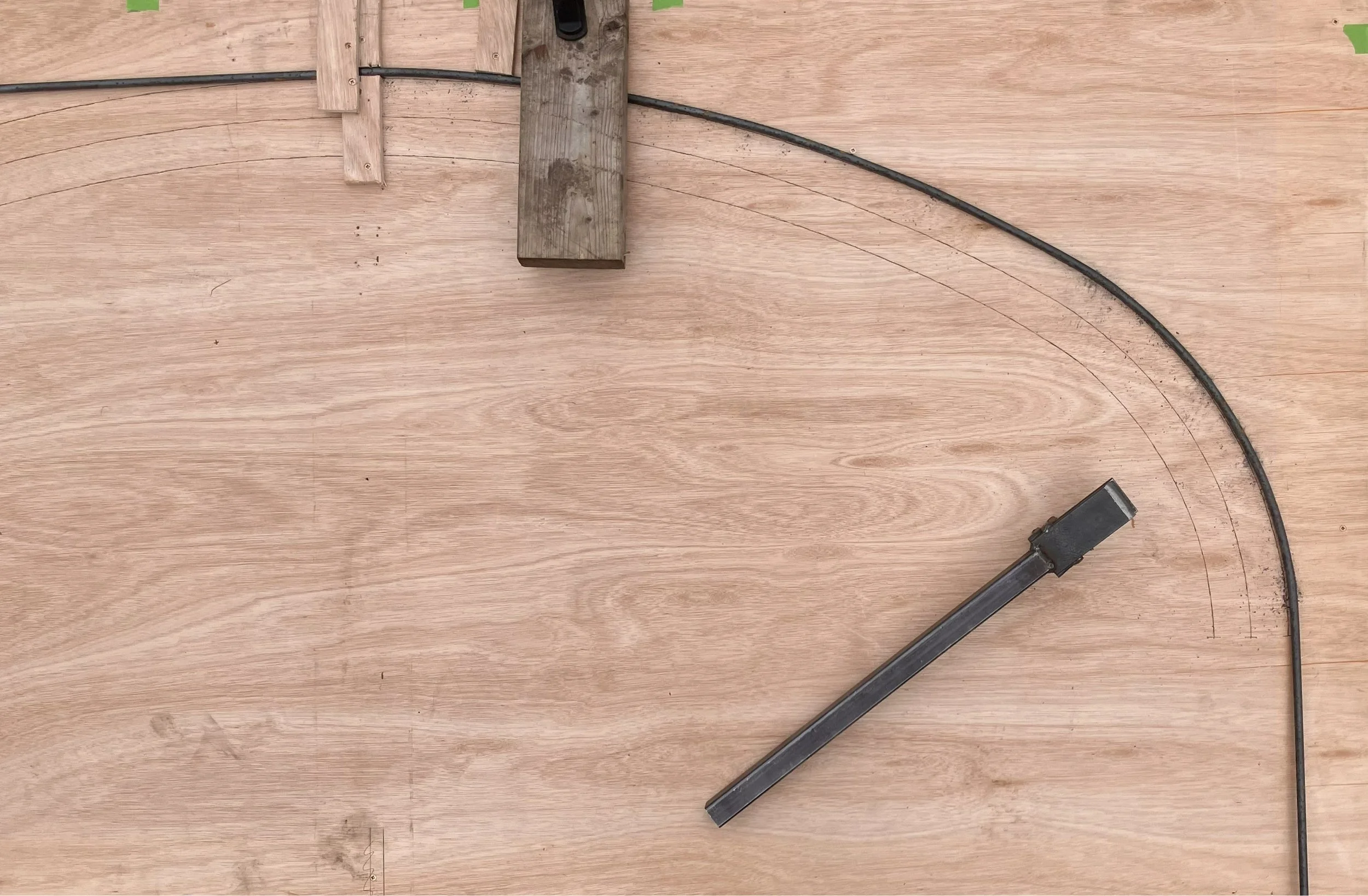
Forming the individual arch section pieces. Outer x 1, middle x2 & inner x 1 for this first arch assembly.
From here we built a base frame using the CAD dimensions to accurately map the footprint where the arch feet will sit. The six pre-drilled base plates were then bolted to this frame. This frame was also used as a jig to join each of the four steel arch sections together with the steel rings.
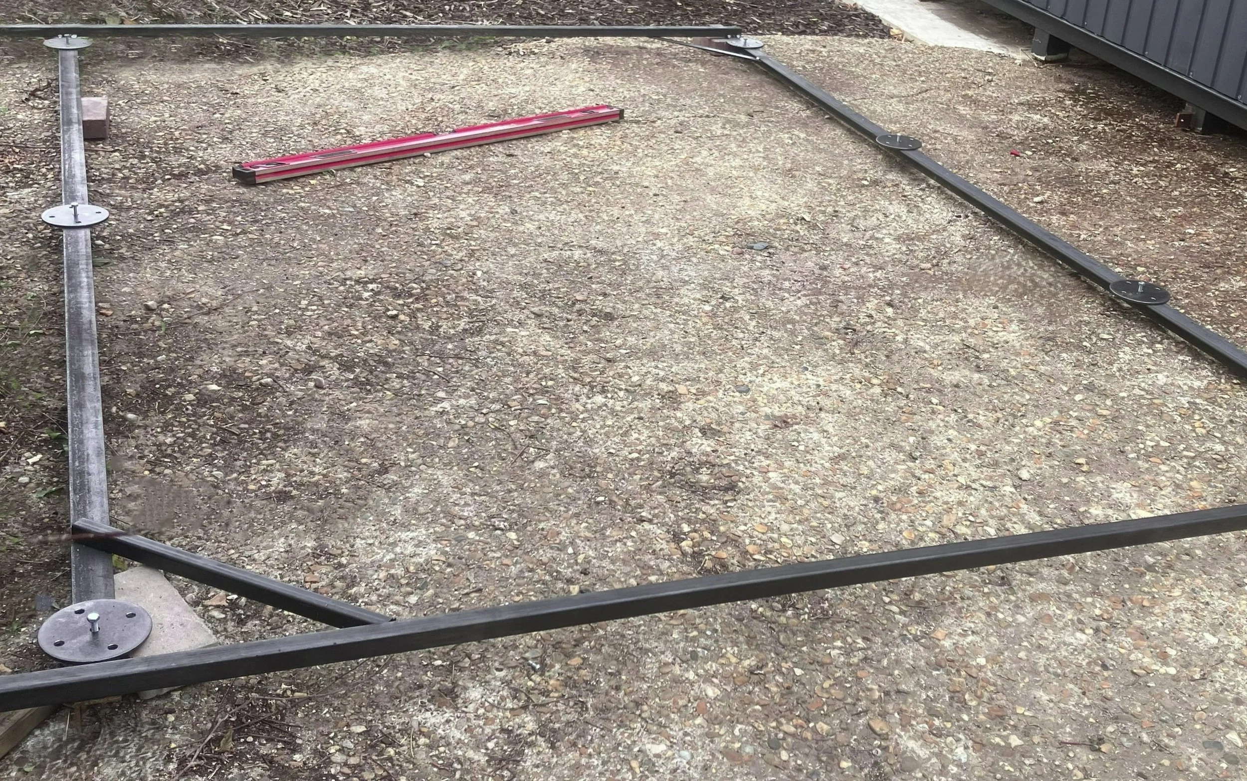
Temporary base frame for mapping the three arch section placements.
Joining the arch pieces together using the base frame as a jig.
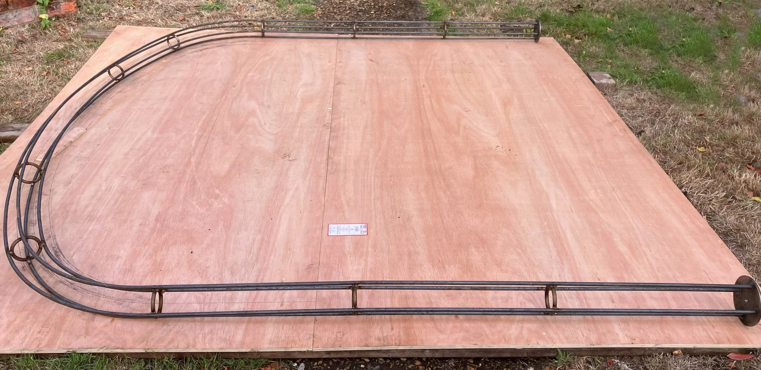
One arch completed.
Now to repeat this whole process two more times…
Once the three arches were completed, we then mounted these to the base frame. These were then joined together with solid steel bar sections.
At this stage, we welded in three pairs of bolt-together rings along the longitudinal centerline apex, then split the whole structure to enable easier transportation & final assembly on site.
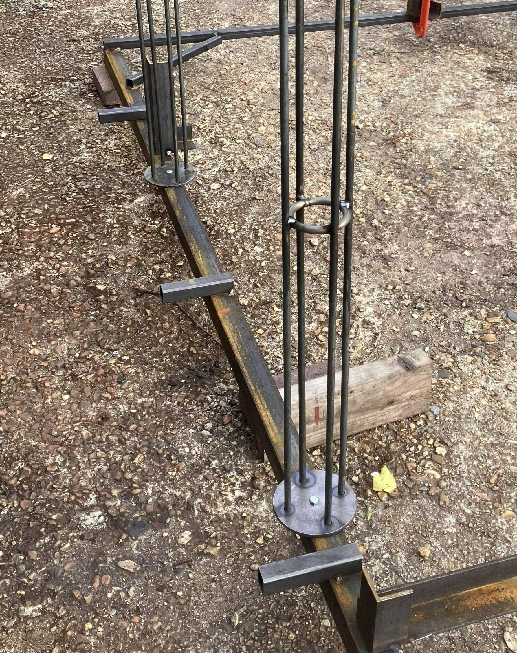
Placing the arches in their respective locations to the base frame.
The final stage was to wrap (weld) the whole structure in steel mesh. This would be the moment of truth and why accuracy was so important, wrapping the heavy steel mesh would determine whether all the geometry would accurately line up. Thankfully, it did…perfectly.
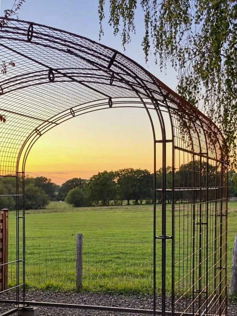
Archway during wrapping process.
Archway installed.
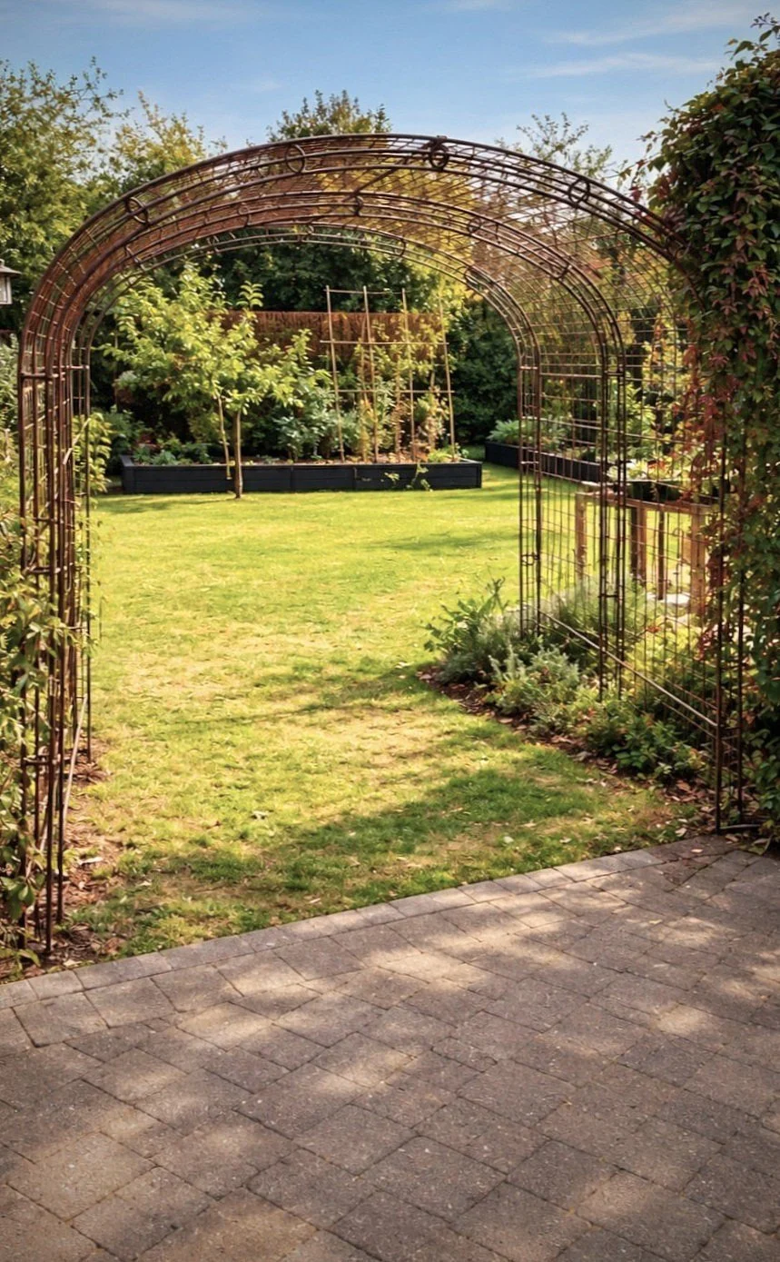
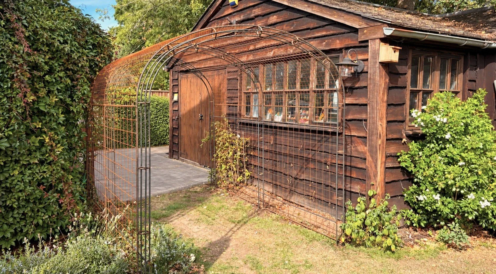
Thank you for following along. Hopefully, you enjoyed reading the process of building a totally bespoke archway to fit in with the surroundings
We enjoyed the challenge!